
14 Beginner Tips to Create a Floor Plan in Revit
Recently, a friend was trying to convince me that Revit was a terrible tool to quickly draw a floor plan. In his opinion, you should use AutoCAD to draw the conceptual plan and only switch to Revit when you are ready for construction documents. Obviously, I strongly disagreed with him. I decided to create a guide that shows the best way to quickly create a floor plan. In this post, we might not follow the BIM best practices or create a fancy 3D model. The goal is to produce good looking floor plans.
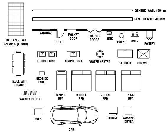
We have prepared a simple template that you can use to create your own floor plan. It contains wall compositions, view templates and components to help you out. You have everything you need to complete the floor plan of a house. You will find all these components in the view called 02-LEVEL 1.
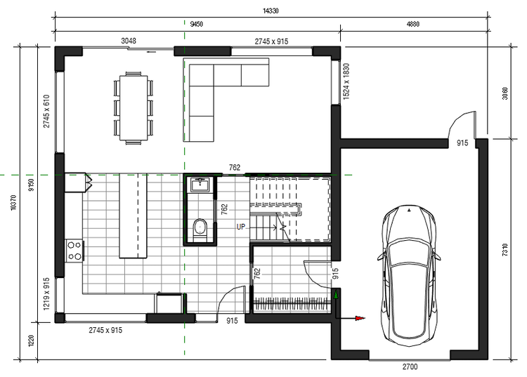
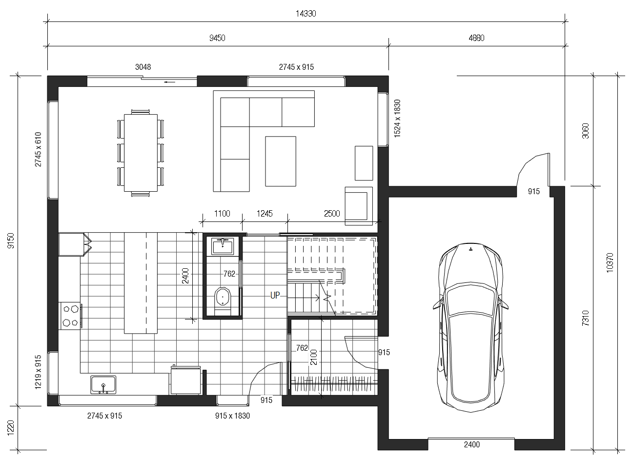
You will also find images of the completed layout in case you want to follow along.
1. Set Up Levels Height
Even if you don’t need elevations or 3D views at the moment, you still need to assign the walls to specific levels. Go to an elevation view to make sure all the required levels are created. Set them to the correct height, although you can adjust later on.

2. Place Walls Intersection at Internal Origin
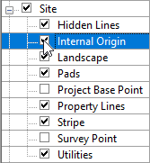
Although you might not care about the coordinate system, you should still place one of the corner of the building at the intersection of the Internal Origin of the project. If you are using Revit 2020.2 or later, the internal origin is indicated by the arrows symbol. The internal origin is not to be confused with the Project Base Point and Survey Point, although all these points should be at the same position when you get started.
If you export to CAD, this point will be used as the origin. Same thing if you link CAD or other format.
If you are confused about Revit’s coordinate system, make sure to check out our popular guide over here: https://revitpure.com/blog/13-tips-to-understand-revit-base-points-and-coordinate-system
Use shortcut VG to go to the Visibility/Graphics menu. Scroll down to find the site submenu. Check the Internal Origin box. The arrow symbol should appear in your plan view.
Create walls at the intersection of the origin.

3. Optional: Create Layout with Detail Lines
One of the most common complaint from AutoCAD users is that there is no way to create a quick layout in Revit. That’s not quite right, you just need to use the proper tools.
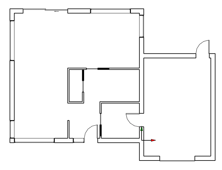
You can create a layout using walls directly, but you can also create a layout using detail lines. Use shortcut DL. These lines are only visible in a single view and are not part of the 3D model. You should use colored lines to distinguish from the model elements. In the example below, we use red lines.
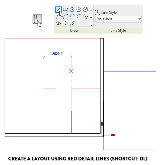
After creating a draft layout, there are multiple you can match your walls and other elements to the detail ones. The best way is probably to use the Align tool (shortcut: AL). Type AL, click the detail line reference, then click the edge of the wall. The wall will move to be aligned to the detail line.

4. Use Shortcut CS to Create Similar
Want to save some time? Select an element and use shortcut CS to create a similar one. This is one of the best way to be efficient. In the example below, we use this tool to quickly create walls.

5. Use Temporary Dimensions
Select an element. You will see a dimension in blue. This is called a temporary dimension. Drag the dots to adjust the witness lines. Change the blue text value to adjust the dimension. Click on the dimension symbol to make the dimension permanent in the view.

6. Use Trim to Quickly Adjust Walls
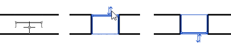
Former AutoCAD users might be familiar with the TRIM (shortcut: TR) tool. Use it to Trim or Extend elements to be joined together.

The same TRIM tool can also be use to extend elements. In the example below, we join two walls.

With the use of detail lines, align, temporary dimensions and trim, you should be able to complete a layout.

7. Add Windows and Doors, Adjust Families Type
Once your wall layout is complete, you can start to add doors and windows. Using shortcut is a great way to save time:
DR - Door
WN - Windows
WA - Walls
Spacebar - Flip door, walls and windows orientation.
In the example below, we use both the standard door and pocket door families. Make sure to use the correct type in the type selector.


Doors are easy to create and control. Click the arrow symbol or hit SPACEBAR to flip the door.

You can start adding windows. Click on the wall, then make sure the side is properly placed. The arrows symbol is located on the exterior side of the window, so make sure to flip it if required.
Create a type of window for each size you need. You can see the effect of the parameters in the example below.
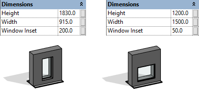
Make sure to also adjust the window sill height like in the example below. It is located in the instance properties.

Our layout now includes walls, doors and windows! Ready for the next step?
8. Add Components and Lines
This is the part where many people might struggle. Finding good components in Revit isn’t as easy as it seems. We made it easy with the link above to download all sorts of useful 2D families for plan views. 2D families are great to quickly produce a plan view, but make sure to upgrade them to 3D elements when you are ready for 3D views.
Start adding components provided in the template. Use the Create Similar tool (shortcut CS) or simply copy/paste. Below, we start adding toilet, fridge, wardrobe rod, fridge, etc.
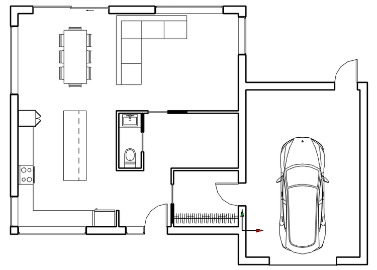
To complement the families, you can use Model Lines (shortcut: LI). In the example above, we use lines to represent the kitchen countertop. Later on, we can model actual cabinets to use in elevations and 3D views.
Each component family might work in a different way. For example, the toilet family has to be hosted on a wall. It can’t just be floating around.

The wardrobe rod family has arrows to control the length of each instance.

Take time to have a look at each family to understand how they work.
9. Use Overlay to Visualize Other Floors
Let’s say you are ready to model the second floor and you already created a stair (you might like our epic blog post about stairs.)
It’s always helpful to see what’s going on below. In the instance of the second floor view, activate the Underlay and set the Base Level to Level 1. The level 1 floor plan will appear in gray. The floor can be used as a reference

10. Use Reference Planes to Align Components From One Floor to Another
Another way to reference position on multiple levels is to use reference planes. These elements appear in dashed green line and never print. In the example below, we add 2 reference planes where we plan to add a structural column at some point. The planes are visible in all plan views.

11. Model Thin Floor For Finishes
Your floor plan is starting to get quite complete! You probably want to show ceramic floor pattern. Create a new floor using a thin type (12mm or 1/2’’). In the template provided, you will find such a type. It includes a 305mm x 610mm (12’’ x 24’’) ceramic pattern.

12. Annotate the Drawing
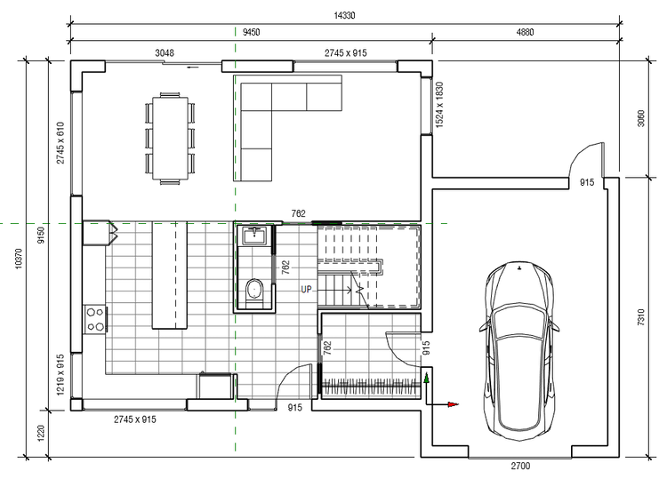
The template include tags for windows and doors. The door tags indicate the width, while the windows tag includes the width x height.
To create tags, use shortcut TG and click on an element.

Tags are intelligent: if you modify the width of the door, the tag will automatically adjust.

In the options bar, you can switch the tag from horizontal to vertical.
Use tags on all doors and windows. You can add dimensions too if you’d like (shortcut: DI).
13. Create a Dark Wall Poche
Why not add a dark wall poche to create a nice presentation effect? Go to the Visibility/Graphics menu by using shortcut VG. Scroll down to the wall category. Click on Cut Pattern. In the background category, set a dark gray color (or black). Use the solid fill option.
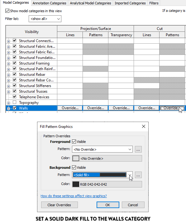
As you can see below, all walls in this view are affected by this setting.
14. Place the Views on Sheets and Print
Make the final touch-ups, then place the view on a sheet. Adjust the crop region of the view around the house. Adjust information on the sheet. You are now ready to print! Good job.

Did you enjoy this post? You will love our newly updated BASICS 2021 learning package. This package has been downloaded thousands of time.
This article was originally published on RevitPure’s blog and has been republished here with permission.

cover image © RevitPure


