Best Tips of Working with Point Clouds in Revit
Editor’s note: This post was originally published on RevitIQ's blog and re-published here with permission.
3D Laser scanning and Point clouds are becoming much more common place in the design process. This is especially true when working with existing structures, where as-built accuracy is extremely important. Point Clouds can be used as an accurate guide for us to create a Revit model around, and provide real-world context for visualization purposes.
Revit makes it easy to import and work with Point Cloud data. In this blog post, I’ll outline some of the steps and tips to get you going.
IMPORTING POINT CLOUDS INTO REVIT

Importing Point Clouds into Revit is much like linking a Revit/CAD/IFC file. On the Insert tab under Link, click on the Point Cloud button.
Next, specify the file or files you want to insert. You can choose from:
.rcp Point Cloud Projects file – (a combination of multiple Point Clouds)
.rcs Point Clouds file – (indexed raw format files), or
any of the Raw format Files. If you employ a 3rd Party company to undertake the Laser Scanning for you, they should be able to provide you with a .rcp file.
Next, you have to select the Positioning for inserting your Point Cloud. Again, much like importing Revit/CAD/IFC files, you can choose from Auto – Center to Center, Auto – Origin to Origin, Auto – By Shared Coordinates, or Auto – Origin to Last Placed. How you insert the Point cloud is up to you and depends on the project and Point cloud.
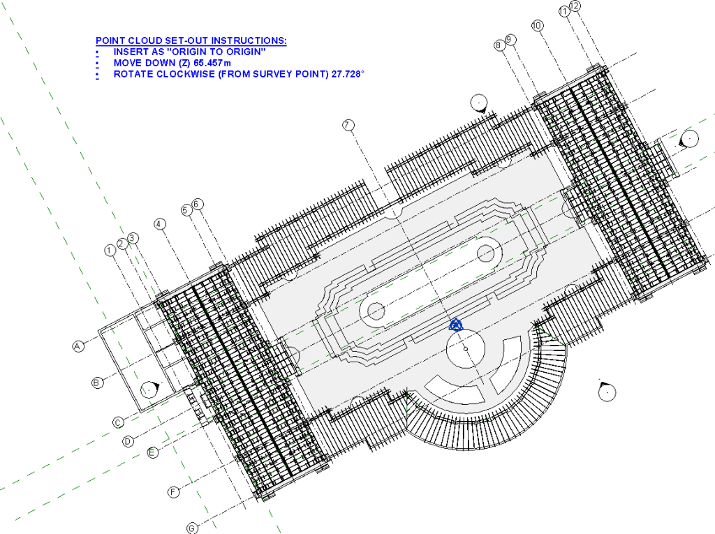
Whatever the case, a good tip is to write down (Ideally within the Revit file) what you did to get your Point Cloud in the correct position, particularly if you inserted a Point Cloud into an existing model. For whatever reason, some times the Point Cloud file or link will get changed and you will have to re-insert the Point Cloud. It’s much easier to insert it back into the exact same place if you know what you did the first time!
DISPLAYING POINT CLOUDS
The visibility of Point Clouds is View specific. You can hide or change the appearance of Point Clouds by using Visibility Graphics. Under the Point Clouds tab, you can edit the Color Mode of the Point cloud which changes the appearance of the Points.

RGB
When the laser scanner shoots points, it also takes a photo by which each point gets assigned a color based off the same point in the photo (Cool huh?!) This is the best Color mode in my opinion and the one I use the most. Basically it looks like a 3D photo which you can walk through! It’s great for 3D views and visuals.

Single Color
Single color is self explanatory, the point cloud gets displayed in a single color which you can choose. It’s not very helpful in 3D views, but is great for Plan Views and Sections.
Elevation
This grades each Point color based on its Z value. I don’t really see the point in this option and never use it to be honest.
Intensity
Intensity is a measure of point reflectivity, which can vary depending upon a surfaces texture and angle. This color mode is fairly helpful when differentiating between different surfaces (such as steel vs concrete for instance).

Normals
This one is hard to explain, but each point is displayed base on the normal direction of the point. Basically it’s helpful for seeing which angle or plane a surface is on. (The color scheme is built-in and is un-editable)

WORKING WITH POINT CLOUDS
Now that we know how to see and alter the appearance of our Point Clouds, we can start to use them to create our Revit Model. The best way to start is to set-out our Levels and Grids relative to the Point cloud. We do this by creating Plans and Sections with a very small View Range (say 150mm). The larger the View Range the more “fuzz” and interference you will see, too smaller View Range and you won’t see enough Points.
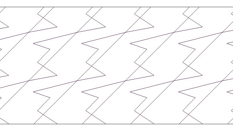
I like to start by cutting a section through the Point Cloud and adding Levels, using the Point Cloud as a guide. As we can see from the section below, we can easily see the Floor level, T.O Columns, and Roof structure.

I then Set out the Grids in a Plan View. As we can see from the Plan View below, we can easily see the Outline of the Columns and Walls.

And that’s basically how it’s done! Move your Section (with the small View Range) around your Point Cloud so you can see whats going on. Notice how I use ‘Single Color’ Color Mode for the plans and sections, and I make it Red so it stands out. This makes it easier to see the outlines of walls & columns etc.
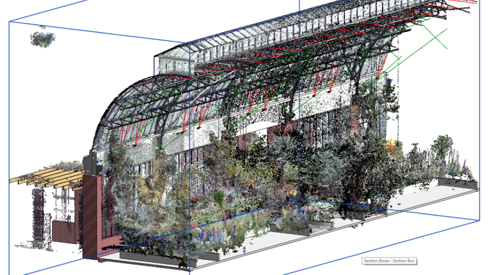
Section Boxes
Point Clouds are great, but they can slow down your Revit session, especially if you’re navigating in 3D and your Point Cloud is quite Large. Use a section box to zero in on the area you’re working on. This reduces the amount of visible elements that Revit has to process.


Working with Point Clouds is a great way for us to accurately model Existing structures. Hopefully this blog post has helped you get a grip on how we do it.
If you have any questions, or have some more tips for Working with Point Clouds in Revit then please leave a comment on Revit IQ's blog here.