
Revit Architecture: An introduction to Ceilings
Editor’s note: This post was originally published on BIMSCAPE's blog and re-published here with permission.
In this Revit Architecture tutorial, I am going to show you how to create Ceiling elements both “Automatically” and by means of the “sketch method"
Tutorial Agenda
Creating Ceilings automatically
Creating Ceilings by Sketch
Aligning Suspended Ceiling Grids
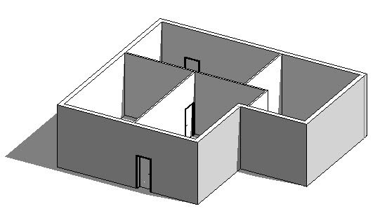
Just like Floors and Roofs, Revit Ceilings consist of 3D model geometry and non-graphical parametric data. They are created by use of the dedicated Ceiling tool. There are 2 methods of creating Ceilings- each with their own pros and cons, which I will explain at the end of the tutorial. To make this tutorial a little more realistic, I have created a simple building to which we can add some Ceiling elements:
If we take a look at this model from the side (using an Elevation View), you can see that it has 3 Levels. I have created a dedicated Level for the Ceiling Height:

Before we actually create any Ceilings, switch to a Ceiling Plan View. These Views are Reflected Ceiling Plans- meaning they simulate an architectural plan where you are looking up at the Ceilings, rather than down at the floor. Ceiling Plan Views have their own Group, which is located directly beneath the Floor Plan Group in the default Project Browser organisation

I am going to switch to Level 0 Ceiling Plan View. This is as if I am standing on the ground floor, looking up at the ceilings. This View is shown below. Note how the Cut Plane is actually above door head height- i.e. we cannot see any door openings in this view:

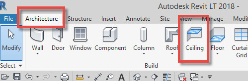
So now that we are in an appropriate View, we can go ahead and create our Ceilings. To do so, you need to use the Ceiling tool, located on the Build panel of the Architecture menu
When you select this tool, you’ll notice that the Ribbon changes to give you two options for creating your Ceilings:

You can either chose:-
Automatic Ceiling: This will make Revit detect where there are bounding Walls that enclose potential ceiling spaces. In short- Revit is going to try and guess from your model where ceilings should be created.
Sketch Ceiling: This allows you to sketch (albeit precisely) where you want your Ceiling elements created. This is a similar process to the one we used in the Floors tutorial.
To start with we will take a look at the Automatic Ceiling option. With this selected, simply hover your cursor over the internal spaces of your model, in the active Reflected Ceiling Plan View:

Notice as you move your cursor around, the bounded room areas highlight with a red perimeter line if Revit is able to form a Ceiling at that location. Basically, Revit is offering you different locations in which to create a Ceiling. To do so all you have to do is click your mouse button when the appropriate area has a red boundary line showing.
Just as we saw in the Floors tutorial, you can change the type of Ceiling you are creating by means of the drop-down Type Selector in the Properties Palette. For this tutorial I am going to switch the type to “600x1200mm_Grid” so that it’s easier to see where we have created the elements- as they will have the grid hatch pattern on them:

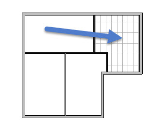
So in the image below you can see that I’ve added a Ceiling element to the room in the top right corner of the building:
Before we go any further, let’s just create a quick section through the building so that we can see the Ceiling elements we have created:

And here is the corresponding Section View:

Note the Ceiling elements in place, just above the height of the “Ceiling Level” Level. For these Ceiling elements, I have referenced them to Level 0 (the Ground Floor)- they then have an Offset to determine their height above that Level. Alternatively we could set their Reference Level to be “Ceiling Level” and have an Offset height of 0. This would then give us the flexibility to adjust height of all the Ceiling elements (that we have referenced to this specific Level) by simply adjusting the height of the Level itself. This would save having to adjust all the parametric “Offset” values of the Ceiling elements.
So that’s how we create a Revit Ceiling automatically. Let’s now take a look at the second method- Sketch Ceiling:

When we use the “Sketch Ceiling” option, Revit immediately enters Sketch Mode. Before we proceed, make sure that the options on the Ribbon are set to (1) “Boundary Line” and (2) “Find Walls”. We can of course manually draw the Boundary Lines where we would like the perimeter of the Ceiling to be. But by using the “Find Walls” tools, Revit will allow us to quickly find the walls we are interested in and create Boundary Lines along them:

So now I can just hove over the Walls in my model (still using a Reflected Ceiling Plan View). With each click of the mouse, Revit places a Ceiling Boundary Line along the length of the corresponding wall:

What I’m trying to do (in the image above) is create a Ceiling element in the room in the bottom-left hand room of the building. I’ve enclosed this space with Boundary Lines- however, they sail way past their intersections. I need to tidy them up by trimming them. To do so just switch to the “Modify” menu and select “Trim”:

With the “Trim” tool selected, go ahead and click on each pair of converging Boundary Lines. Ensure you click on the portion of the lines that you wish to KEEP- not the portions you wish to discard! After you have gone round all 4 corners of the room, you should end up with a neat Boundary sketch that looks like this:

Now that we have told Revit where we want the perimeter of our Ceiling element to be, all that is left to do is hit the Green Tick! This instructs Revit to create the 3D model geometry of the Ceiling element to the specification (ie the Type) and dimensions / shape (ie the Sketch) we have stipulated:

In the image below you can see the new Ceiling element we have just created by means of the “Sketch Ceiling” option:

Let’s now cut an opening in one of these ceiling elements. Go ahead and select the lower lefthand suspended grid ceiling. You may need to use the TAB key in order to get Revit to find the edge of the ceiling element, as opposed to the wall:

Once you have selected the ceiling, you will see (on the Ribbon menu) that there is now an option to “Edit Boundary”:

Go ahead and select “Edit Boundary”- Revit immediately goes back into Sketch Mode. Choose any of the tools on the Draw palette that you wish to use to draw the boundary of your aperture. I am going to use the Circle tool:

With the tool selected, I can draw a circle in the middle of my ceiling panel. Please ensure that this “inner closed loop” does not touch the existing boundary (pink lines) of the ceiling. Also ensure that it is a “closed” loop- ie that it has no open ends:

Once I have sketched out the shape of the aperture, I can hit the Green Tick and get Revit to recreate the ceiling element complete with the new opening. If I switch to a 3D view we can clearly see the opening in the ceiling:

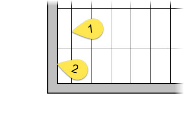
And finally I will conclude this tutorial by showing you how to align your suspended ceiling grids with the edge of the room. In reality when you are setting-out a suspended ceiling you either want to start with a whole tile or (at least) a good propoirtion of a tile- no small slivers of tiles that are hard to fit! So in the image below we would like a grid line (1) to start at the wall boundary (2):
The grid that you are actually seeing on the ceiling is a model hatch pattern. And as such, it can be realigned using the “Align” tool. So if you switch to the “Modify” menu and select the “Align” tool

With the Align tool selected, you need to first click on the element that you wish to align TO- in this case it is the edge of tghe wall (1) and THEN you click on the element that you wish to actually align- the grid line in this case (2):

Upon the second click, Revit shifts the grid over so that (in effect) the ceiling starts with a whole panel. Notice that on immediate completion of the Align process, Revit offers you the opportunity to “constrain” this new relationship- ie keep the grid line ALWAYS aligned with the edge of the wall. If you would like to have this constraint put in place, simply lock the Padlock by clicking on the icon

Now if you subsequently move the external wall (the client wants a larger room for example), the ceiling grid will automatically move with it and (consequently) start with a whole tile. Thus, one less this for you to manually coordinate!
Key Points:
Revit Ceilings are System Families
Ceilings can either by placed automtically or their boundaries can be manually sketched
Apertures can be formed in ceilings by adding a closed loop to their boundary sketch
You can also use a “Shaft Opening” object to cut an aperture in a ceiling element
Grid lines on the ceilings can be moved / realigned by using the Align tool
Editor’s note: This post was originally published on BIMSCAPE's blog and re-published here with permission.
cover image © unsplash

