Editor’s note: This post was originally published on BIMSCAPE's blog and re-published here with permission.
In this Revit Architecture tutorial, I’m going to show you how to get started with Floor Elements. For the purposes of this tutorial, we are going to work with Architectural Floors, rather than the Revit Structural Floor element.
Tutorial Agenda
Floors are System Families
Sketching the boundary of your floor
Floor Types
Editing the Floor Structure
Changing the boundary of your floor
Adding openings to your floor elements
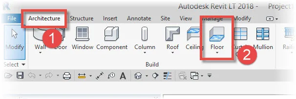
So let’s get started and create a basic rectangular Floor element. I’m just going to work with a new, blank Revit Project for this tutorial. All you need to create a Revit Floor is a Level for it to reference- you do not need Revit Walls (or columns, beams, etc) top support the Floor element. To create a Revit Floor, access the Architecture menu, the Build Panel and then select Floor:
As soon as you hit the “Floor” icon, you will be presented with sub-options- Architectural Floor, Structural Floor and Floor: Slab Edge. I’ll be covering the 2nd and 3rd options in other tutorials. For now let’s stick with Floor: Architectural:

With “Floor: Architectural” selected, Revit immediately enters “Sketch Mode”. This is confirmed by the presence of the Red Cross and Green Tick on the Ribbon menu. Sketch Model allows us to sketch out on screen the perimeter boundary of our Floor Element. Make sure that (1) “Boundary Line” is selected and (2) the Draw Palette option is set to Rectangle:

We’re now ready to sketch out the perimeter of our Floor element. Obviously ensure you are in a Plan View to do this.Because we have the “Rectangle” Draw tool enabled (see no.2 in the above image)- we can simply click on two opposite corners of the rectangle to make Revit create the 4 Boundary Lines of our Floor (see no.1 below). When you do this, Revit will also add 2 additional short lines to one of the four sides- see no.2 below. Do not worry about this! These lines are the “Floor Span Direction’ icon. They show you which way the floor spans, structurally. This can always be altered afterwards.

The thing to note with your Boundary Lines is that they must form a continuous single boundary around the perimeter of your Floor Elements. No extraneous lines please! No line extending past the corners- Revit will not be happy and will not accept the Sketch! Ok so we have the perimeter of the Floor sketched out. Now go ahead and choose the “Type” of Floor you want from the drop-down list in the Type Selector:

For the purposes of this tutorial it does not make any difference which Type you choose. Just note that you can either choose the Type now (whilst we are in Sketch Mode) or after we have completed the process of making the 3D geometry. So we have a sketch and a chosen type. All we need to do now is hit the Green Tick and let Revit create the 3D geometry of the Floor Plate, according to the data we have given it:

If I switch to a 3D View, you can see the completed Floor Plate:

Note how the Floor element is actively selected (as displayed in blue) immediately upon completion of it’s creation. Let’s now create a Section View through the finished Floor. In the image below you can see that I’ve placed a Section line across the middle of the floor:

Let’s switch the Section View associated with this Section Line. Ensure that the Detail Level of this View is set to “Fine”. Here is what the Section through my Floor looks like:

There are 2 things to note here:-
That no matter how thick your Floor element is (and this will depend on it’s build-up) it’s upper surface is always aligned with the Level it is associated to.
You can see the various Layers that make up the Floor Type, when you take a Section through it. You can change the order of these Layers (and their thickness, etc) by “Editing the Structure” of the Floor Type.
Let’s now go ahead and add a circular opening into our Floor element. Firstly go ahead and ensure that the Floor is selected in the active view. As soon as you have the Floor element selected, you will see the option to “Edit Boundary” on the Ribbon menu:

When you select “Edit Boundary” you are immediately taken back into Sketch Mode- exactly the same place we were at the start of the tutorial when we were creating the basic geometry of our Floor element. This time we are going to use the “Circle” tool on the Draw Palette, rather than the “Rectangle”:

We can place a circle anywhere “inside” of our (original) rectangular boundary. PLEASE make sure this circle does NOT cross or touch the outer rectangular boundary. If you do so, Revit will reject the new sketch, with errors.

With our circle in place, we can now go ahead and get Revit to remake the 3D geometry of the Floor element, based upon this new sketch. To do so, just click on the Green Tick on the Ribbon menu. Revit immediately recreates the floor, complete with circular aperture:

Key Points
Revit Floors are System Families (i.e. created in the software, at the time you need them)
You use Sketch Mode to sketch out the boundary of the floor you wish to create
You can nest “closed loops” inside of the outer boundary in order to form openings
All of your Boundary Lines must form closed loops
Editor’s note: This post was originally published on BIMSCAPE's blog and re-published here with permission.
