Mastering 9 Revit Railings Advanced Properties
3 Types of Rails
Top Rail: Top rail is the highest horizontal element of a railing. It is created by selecting a 2D profile and a height.
Handrail: Handrail is an intermediate rail used for hands. They are linked to a wall or to a railing with Supports.
Intermediate Rail: Any horizontal rail other than the Top Rail and the Handrail. Can be used to constraints balusters. Also known as Non-Continuous Rails.

Top Rail

Handrail

Intermediate Rail
Top Rails and Handrails have their own system families. They can be found in the project browser. Different types can be used on different railings.

In the railings properties, you can select a Top Rail type and set the height. Click the 3 small dots to access the top rail properties.

In the railings properties, you can select a Top Rail type and set the height. Click the 3 small dots to access the top rail properties.

As for Intermediate Rails, they are created directly in the main Railing type properties. Access the menu by clicking on Rail Structure (Non-Continuous). Then, set setting properties like Height, Offset, Profile and Material.


Top Rail Properties

Handrail Properties

Intermediate Properties

Comparing 3 Types of Rails


Understanding 9 Rails Parameters
1. Assign to Balusters
Balusters base and top can be constrained to rails, except for handrails.
In the image below, you can see we constrain a baluster base to an intermediate rail (also known as non-continuous rail). The top of the baluster is constrained to the Top Rail. Offsets can be assigned to the base and top.

2. Creating Rail Profile
Create a new profile family using the Profile - Rail default template. Use the text guidelines to properly draw the profile.

In the top rail properties, make sure to select the profile you have just created. The Hand Clearance value will be set so the profile is automatically centered with the railing boundary line. (see property #5)

We got our top rail profile. Yeah!

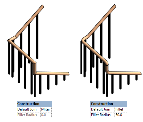
3. Default Join: Miter or Radius
Most top rail Default Join parameters are set to miter, producing a standard, straight transition. You can go to the Top Rail or Handrail type properties and change the Default Join to Fillet instead of Miter. Then, you will get access to the Fillet Radius value. This affects all transitions, both in the horizontal and vertical planes.
Modify Individual Join
In the previous tip, changing the default join affected all joins. What if you want to modify an individual join instead? You will have to select the top rail using tab. Then, click on Edit Rail. Click on Edit Path.

Then, you’ll have to click on Edit Rail Joins.

Click on one of the join, represented by the square snap symbol. Then, change the join type to Fillet and enter the radius value you wish to use.

If you enter a value that is too big and would interfere with another intersection, you will get the following warning:

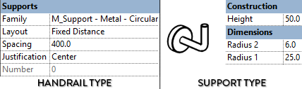
4. Supports
Supports are used to connect Handrails to railings or to walls. Adjust Family type, Layout, Spacing and Justification in Handrail type.
The default Revit family is Circular. In the Support Type properties, you can adjust Radius and Height. If you want a different shape, you will need to create another Support family.

There are 5 different layout options for supports:

Layout Options Examples

Support Tips
You can unpin and move a support to get a specific position.

When a support is placed on walls of different distances, you can individually select a support and set an individual Hand Clearance value.

5. Hand Clearance
The Hand Clearance value represents the distance between the railing path (represented by a purple line) and the beginning of a rail. In the example below you can see a few different values use on a Top Rail, showcased in a plan view.

Projection Value is Automatically Created
Just next to the Hand Clearance value in the properties, you will find the Projection value. This represents the distance between the railing path line and the end of the rail. This value is only for information purpose: it can’t be modified. It is automatically generated by adding the Hand Clearance to the rail’s width. In the example below, you can see the projection is equal to the Hand Clearance (50mm) added to the width of the rail (40mm).

Flip the Direction of the Railing
By default, the hand clearance value is relative to the interior side of the railing. That’s quite obvious when you are hosting the railings on a stair, but less so when you are drawing a railing on the ground. If the hand clearance puts your rail on the wrong side, click the flip arrows to switch sides.

Hand Clearance Guidelines
The top rail is usually centered on the railing path line. Actually, Revit will automatically set the Hand Clearance value to -(width/2) so the profile is perfectly in the middle. Hand clearance is usually more useful for Handrails, where code standards often requires you to have a minimum value.
6. Transitions
There are 3 transition types for Handrails and Top Rails in Revit. Simple, Gooseneck and None. Look at the image below to understand what all these transitions actually do:

In the strange railing below, the Top Rail has Gooseneck transitions and the Handrail has Simple transitions.

7. Terminations
Terminations are located at the end of a Top Rail or Handrail. In the example below you can see the difference between a top rail using a termination and one using no termination. People are less likely to stab themselves in the stomach when a termination is used :)

The default Revit termination family is a simple plate of wood usually set against a wall and used for handrails.

Creating a Termination Family
Create a new family and use the Railings - Termination family template. Model the geometry of the termination on the right side of the reference planes, where the red lines are drawn in the image below.

To recreate the ancestral termination used in the previous page, load the profile in the family and model a sweep. Then, create a void extrusion to cut the extremity of the sweep. Load the family in your project.

Assign Termination to Rail
Terminations can be assigned to Top Rails and Handrails. In the example below, we start by assigning terminations to the Top Rail. We assign a termination to both the Beginning and the End of the rail. Then, we assign terminations to the handrails. Why not?


Remove Termination Line in 3D Views
As you can see, there is an annoying line that joins the rail with the termination. You can get rid of it in a 3D view by using the Lineworks tool (shortcut: LW). Select the <Invisible Lines> type and click a few times on each visible line you want to remove. This only affects the visibility of the lines on a single view.

Termination is Places at End of Path
Are you using a custom end path for the railing? The termination will be placed at the end of the custom path.

8. Extensions
Now, let’s talk about extensions. You will find these options in the Top Rails and Handrails properties. You can set an extension type and a value. You set whether the the extension is at the beginning and/or end of the railing. The Wall extension type only works with handrails.

As you can see below, an extension value goes beyond the purple path lines of a railing. See next page to understand the extension options.

Extension Styles:

Using “Tread Depth”
When using railing on a stair, you can activate the Plus Tread Depth parameter. This is only available at the bottom of the stairs. In addition to the extension length, the width of a tread will also be added to the rail.

9. Create Custom Extension Path
In the last page, you were limited to 4 extension shapes. Turns out you can customize the shape to whatever you want.


Tab-select the Top Rail or Handrail, then click the Edit Rail button. Then click Edit Path.

Changed your mind and want to go back to the original shape? Click the Reset Rail button when the Top Rail or Handrail is selected.

Editing railing path is limited to the extensions, you cannot modify the main part of the rail. Use this feature for Top Rails or for Handrails.
Custom Path Limitations
A custom path is limited to the current plane of the railing. You can’t draw a sophisticated 3D path. In the image below, the path has to be drawn on the blue plane.

We just went through 9 parameters and features that can be adjusted in the type properties of rails.
Want to get even more advanced tricks about railings? Like how to set a landing height adjustment? Just check out our brand new free pamphlet publications. It contains 44 pages of pure bliss and tips about Revit railings.

This article was originally published on RevitPure’s blog and has been republished here with permission.

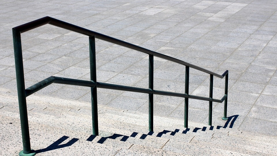
cover image © RevitPure